
In the previous articles, we covered Devicetree in great detail: We’ve seen how we can create our own nodes, we’ve seen the supported property types, we know what bindings are, and we’ve seen how to access the Devicetree using Zephyr’s devicetree.h API. In this fifth article of the Practical Zephyr series, we’ll look at how Devicetree is used in practice by dissecting the Blinky application.
Using a practical example, we’ll see that our deep dive into Devicetree was really only covering the basics that we need to understand more advanced concepts, such as pin control and device drivers.
👉 Find the other parts of the Practical Zephyr series here.
🎬 Listen to Martin on Interrupt Live talk about the content and motivations behind writing this series.
Like Interrupt? Subscribe to get our latest posts straight to your inbox.
Prerequisites
This article is part of the Practical Zephyr article series. In case you haven’t read the previous articles, please go ahead and have a look. This article requires that you’re able to build and flash a Zephyr application to the board of your choice and that you’re familiar with Devicetree.
We’ll be mainly using the development kit for the nRF52840 but will also refer to example files from the STM32 Nucleo-64 development board towards the end of the article. You can follow along with any target - real or virtual.
Note: A full example application including all files that we’ll see throughout this article is available in the
04_practicefolder of the accompanying GitHub repository.
Warm-up
If you’ve been following along, you know the drill by now: Let’s create a new freestanding application with the files listed below:
$ tree --charset=utf-8 --dirsfirst
.
├── src
│   └── main.c
├── CMakeLists.txt
└── prj.conf
The prj.conf remains empty for now, and the CMakeLists.txt only includes the necessary boilerplate to create a Zephyr application with a single main.c source file. As an application, we have a main function that simply puts the MCU back to sleep at fixed intervals:
#include <zephyr/kernel.h>
#define SLEEP_TIME_MS 100U

int main(void)
{
    printk("Message in a bottle.\n");
    while (1)
    {
        k_msleep(SLEEP_TIME_MS);
    }
}
As usual, I’ll build the application for my nRF52840 Development Kit from Nordic, but you can use any of Zephyr’s long list of supported boards - or an emulation target.
$ west build --no-sysbuild --board nrf52840dk/nrf52840 --build-dir ../build
Devicetree with gpio
Let’s start with a classic: The blinking LED. The easiest way to control a low-power LED is using a GPIO, and one obvious way to approach this problem is to jump straight to the gpio API documentation. In contrast to Zephyr’s OS service documentation, however, the documentation for peripherals is typically restricted to the API, without further explaining the subsystem.
Instead, Zephyr’s chosen approach is to provide a list of related code samples for each subsystem, showing the API in action. And Zephyr comes with hundreds of samples and demos! In the list of related samples for the gpio subsystem, we also find the good old blinky example.
Note: Blinky is an example for a Zephyr repository application. We continue using a freestanding application, and in the next article, we’ll finally create a workspace application.
Straight from the documentation, we follow the “Open in GitHub” link to find the application in Zephyr’s repository and simply copy the contents from main.c into our own application. We’ll now compare the gpio Devicetree API with the “plain” API in zephyr/include/zephyr/devicetree.h that we’ve seen in the previous article.
Blinky with a /chosen LED node
The Blinky example chooses the LED Devicetree node using the alias led0. Zephyr keeps its Devicetrees clean and we’ve seen that aliases, including led0 are usually consistent throughout supported boards. Thus, if there’s a board supported by Zephyr that has at least one light on it that works like LED, you can be sure that there’s also a matching led0 alias:
zephyr/boards/nordic/nrf52840dk/nrf52840dk_nrf52840.dts
/ {
  leds {
    compatible = "gpio-leds";
    led0: led_0 {
      gpios = <&gpio0 13 GPIO_ACTIVE_LOW>;
      label = "Green LED 0";
    };
  };
  aliases {
    led0 = &led0;
  };
};
Since we’re practicing, however, we’ll use a /chosen node called app-led instead. We add this node using a new board overlay file boards/nrf52840dk_nrf52840.overlay for the nRF52840 development kit:
$ tree --charset=utf-8 --dirsfirst
.
├── boards
│   └── nrf52840dk_nrf52840.overlay
├── src
│   └── main.c
├── CMakeLists.txt
└── prj.conf
boards/nrf52840dk_nrf52840.overlay
/ {
    chosen {
        app-led = &led0;
    };
};
In the example application, we use DT_CHOSEN(app_led) instead of DT_ALIAS(led0), but that’s about the only change for the original Blinky sources that we need. Notice that again we specify the chosen node’s name using its “lowercase-and-underscore” form app_led instead of the node’s name app-led in the Devicetree. With a few minor adaptions, our application looks as follows:
/** \file main.c */

#include <zephyr/drivers/gpio.h>
#include <zephyr/kernel.h>

#define SLEEP_TIME_MS 1000U
#define LED_NODE      DT_CHOSEN(app_led)

static const struct gpio_dt_spec led = GPIO_DT_SPEC_GET(LED_NODE, gpios);

int main(void)
{
    int err = 0;

    if (!gpio_is_ready_dt(&led)) { return -EIO; }

    err = gpio_pin_configure_dt(&led, GPIO_OUTPUT_ACTIVE);
    if (err < 0) { return -EIO; }

    while (1)
    {
        (void) gpio_pin_toggle_dt(&led);
        k_msleep(SLEEP_TIME_MS);
    }
}
Building and flashing the application we indeed end up with a blinking LED.
$ west build --no-sysbuild --board nrf52840dk/nrf52840 --build-dir ../build
$ west flash --build-dir ../build
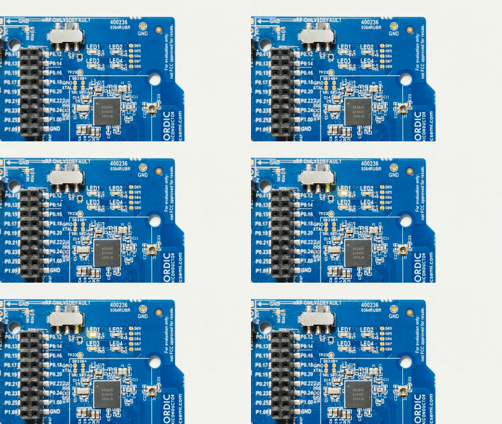
I don’t know about you, but even after all those years a blinking LED still puts a smile on my face.
Dissecting the GPIO pin information type
Looking through the function prototypes of gpio_is_ready_dt, gpio_pin_configure_dt, and gpio_pin_toggle_dt, you’ll notice that they take a “GPIO specification” const struct gpio_dt_spec *spec as a parameter. We find the matching declaration in Zephyr’s gpio.h:
zephyr/include/zephyr/drivers/gpio.h
struct gpio_dt_spec {
  /** GPIO device controlling the pin */
  const struct device *port;
  /** The pin's number on the device */
  gpio_pin_t pin;
  /** The pin's configuration flags as specified in devicetree */
  gpio_dt_flags_t dt_flags;
};
Disclaimer: This section is a nose dive deep into Zephyr’s use of the generated Devicetree files. In case you don’t want - or don’t need - to know about the inner workings, I highly recommend sticking to Zephyr’s samples and demos or the official documentation in general. Skip ahead to the next section about the
statusproperty instead. In case I couldn’t talk you out of it, hold on tight!
Applying the Devicetree API
Let’s ignore the gpio_dt_spec structure’s contents for now. Instead, let’s see how GPIO_DT_SPEC_GET is used to populate the structure and how it compares with what we’ve learned about the Devicetree API in the previous articles:
So far, we’ve only used the macros from the Devicetree API zephyr/include/zephyr/devicetree.h. Now we see how Zephyr’s drivers create their own Devicetree macros on top of this basic API. We can find the macro declaration in Zephyr’s gpio.h header file.
zephyr/include/zephyr/drivers/gpio.h
#define GPIO_DT_SPEC_GET(node_id, prop) GPIO_DT_SPEC_GET_BY_IDX(node_id, prop, 0)
// At some other location ...
#define GPIO_DT_SPEC_GET_BY_IDX(node_id, prop, idx)                 \
  {                                                                 \
    .port = DEVICE_DT_GET(DT_GPIO_CTLR_BY_IDX(node_id, prop, idx)), \
    .pin = DT_GPIO_PIN_BY_IDX(node_id, prop, idx),                  \
    .dt_flags = DT_GPIO_FLAGS_BY_IDX(node_id, prop, idx),           \
  }
Similar to what we’ve seen for our own example in the previous article, Zephyr uses Devicetree macros to create an initializer expression for the matching type that should be used with the corresponding macro. The macros DT_GPIO_PIN_BY_IDX and DT_GPIO_FLAGS_BY_IDX simply expand to the DT_PHA_<x> macros that we used when accessing phandle-arrays:
#define DT_GPIO_PIN_BY_IDX(node_id, gpio_pha, idx) \
  DT_PHA_BY_IDX(node_id, gpio_pha, idx, pin)
#define DT_GPIO_FLAGS_BY_IDX(node_id, gpio_pha, idx) \
  DT_PHA_BY_IDX_OR(node_id, gpio_pha, idx, flags, 0)
Ignoring the .port field (we’ll get to that, don’t worry), GPIO_DT_SPEC_GET expands to a very familiar format, where .pin and .dt_flags are initialized using the pin and flags specifier cells from our Devicetree:
#define GPIO_DT_SPEC_GET(node_id, prop)                              \
  {                                                                  \
    .port = DEVICE_DT_GET(/* --snip-- */),                           \
    .pin = DT_PHA_BY_IDX(node_id, prop, /*idx*/0, pin),              \
    .dt_flags = DT_PHA_BY_IDX_OR(node_id, prop, /*idx*/0, flags, 0), \
  }
Note: The downside of using C macros is that, well, they’re macros. Macros are expanded by the preprocessor, and the preprocessor doesn’t care about types. It therefore also doesn’t care if you use
GPIO_DT_SPEC_GETas an initializer for an incompatible type. This typically fails during compile time in case the assigned variable or constant doesn’t have a compatible type.
Reviewing phandle-arrays
Properties of type phandle-array are heavily used in Devicetrees. Since we now have one at hand with our Blinky example, let’s use it to review what we’ve learned about phandle-arrays - practice and repetition is the key to learning new concepts! The /leds/led0 is defined in the board’s DTS file as follows:
(reduced) zephyr/boards/nordic/nrf52840dk/nrf52840dk_nrf52840.dts
/ {
  leds {
    compatible = "gpio-leds";
    led0: led_0 {
      gpios = <&gpio0 13 GPIO_ACTIVE_LOW>;
    };
  };
};
The matching binding specifies that all child nodes of led have the required property gpios of type phandle-array:
(reduced) zephyr/dts/bindings/led/gpio-leds.yaml
compatible: "gpio-leds"
child-binding:
  description: GPIO LED child node
  properties:
    gpios:
      type: phandle-array
      required: true
Nothing unexpected here: Since gpios is of type phandle-array, we can use it to refer to any of the board’s GPIO instances. Looking at the above binding you might ask yourself: Except for the property’s name, how do we know which nodes we can refer to in this phandle-array?
We don’t.
Looking at the Devicetree in isolation, you can, in fact, use references to any node, as long as the node has the matching #gpio-cells property. You could, e.g., create your own node and binding, where #gpio-cells doesn’t use pin and flags as specifiers. E.g., we could define our own binding custom-cells-a:
dts/bindings/custom-cells-a.yaml
description: Dummy for matching "cells"
compatible: "custom-cells-a"
gpio-cells:
  - name-of-cell-one
  - name-of-cell-two
  - name-of-cell-three
In our board overlay, we can create a dummy node_a with the above binding, and overwrite the property gpio of led0 with a reference to this dummy node:
boards/nrf52840dk_nrf52840.overlay
/ {
    chosen {
        app-led = &led0;
    };
    node_a {
        compatible = "custom-cells-a";
        #gpio-cells = <3>;
    };
};
&led0 {
    gpios = <&{/node_a} 1 2 3>;
};
If we were to revert our main.c file to the original dummy application that doesn’t use the gpio subsystem, the build passes without warnings and we’d find our /leds/led_0 node with the following properties in the merged zephyr.dts file:
build/zephyr/zephyr.dts
/ {
  leds {
    compatible = "gpio-leds";
    led0: led_0 {
      gpios = < &{/node_a} 0x1 0x2 0x3 >;
      label = "Green LED 0";
    };
  };
};
There is no mechanism in Devicetree that allows declaring a phandle-array which is “generic over a type” or “something GPIO compatible”. E.g., there’s no such thing as a base class, interface, or trait that you might know from programming languages.
Even if there was an annotation phandle-array<T>, e.g., to specify the required compatible property, what would we provide for T? GPIO nodes use different models depending on the vendor, e.g., the following snippets show the compatible properties of the GPIO nodes of the nRF52840 and STM32:
zephyr/dts/arm/nordic/nrf52840.dtsi
/ {
  soc {
    gpio0: gpio@50000000 { compatible = "nordic,nrf-gpio"; };
    gpio1: gpio@50000300 { compatible = "nordic,nrf-gpio"; };
  };
};
zephyr/dts/arm/st/c0/stm32c0.dtsi
/ {
  soc {
    pinctrl: pin-controller@50000000 {
      gpioa: gpio@50000000 { compatible = "st,stm32-gpio"; };
      gpiob: gpio@50000400 { compatible = "st,stm32-gpio"; };
      gpioc: gpio@50000800 { compatible = "st,stm32-gpio"; };
      gpiof: gpio@50001400 { compatible = "st,stm32-gpio"; };
    };
  };
};
Sure, both “nordic,nrf-gpio” and “st,stm32-gpio” could claim compatibility with some “base binding”, but there’d always be the odd corner case that doesn’t entirely match the model.
By discarding such a requirement, we gain flexibility - at the cost of “loose typing” within the Devicetree. If we were to try and use the Zephyr GPIO API with the above assignment to gpios, the application would fail to compile since the required specifier cells do not have the names pin and flags read using the DT_PHA_BY_IDX[_OR] macros in the GPIO_DT_SPEC_GET macro. There’s one more thing within GPIO_DT_SPEC_GET that is related to this discussion, can you see it?
#define GPIO_DT_SPEC_GET(node_id, prop)                              \
  {                                                                  \
    .port = DEVICE_DT_GET(/* --snip-- */),                           \
    .pin = DT_PHA_BY_IDX(node_id, prop, /*idx*/0, pin),              \
    .dt_flags = DT_PHA_BY_IDX_OR(node_id, prop, /*idx*/0, flags, 0), \
  }
Looking at dt_flags, we see that GPIO_DT_SPEC_GET uses the _OR variant of the phandle macro DT_PHA_BY_IDX to read the flags from the Devicetree:
- For nodes with a compatible binding that have both,
pinandflagsspecifiers, the Devicetree compiler ensures that values are provided for both,pinandflagswhenever the node is references in aphandle-array; providing a value forflagsis not optional for such phandles. - For nodes with a compatible binding that do not have the
flagsspecifier, the value 0 is used in the specification. The compatible driver can also completely ignore the flags field in any API call.
This adds another level of flexibility to the generic binding gpio-leds for LEDs, supporting any kind of GPIO node LEDs, regardless of whether or not they support using flags, e.g., as follows:
/ {
  leds {
    compatible = "gpio-leds";
    led0: led_0 { gpios = <&gpio0 13>; };
  };
};
Device objects and driver compatibility
We now know how the .pin and .dt_flags fields of the structure are populated, but what about the .port? Let’s try to find out what the macro expands to.
#define GPIO_DT_SPEC_GET(node_id, prop)                                  \
  {                                                                      \
    .port = DEVICE_DT_GET(DT_GPIO_CTLR_BY_IDX(node_id, prop, /*idx*/0)), \
    .pin = DT_PHA_BY_IDX(node_id, prop, /*idx*/0, pin),                  \
    .dt_flags = DT_PHA_BY_IDX_OR(node_id, prop, /*idx*/0, flags, 0),     \
  }
The macro parameters are given in our application and expand as described in the following snippet:
static const struct gpio_dt_spec led = GPIO_DT_SPEC_GET(DT_CHOSEN(app_led), gpios);
// Knowing that `DT_CHOSEN(app_led)` expands to `DT_CHOSEN_app_led`,
// we can look up `DT_CHOSEN_app_led` in `devicetree_generated.h`,
// which is defined as `DT_N_S_leds_S_led_0`.

// Thus:
// - node_id = DT_N_S_leds_S_led_0
// - prop    = gpios
//
// .port = DEVICE_DT_GET(DT_GPIO_CTLR_BY_IDX(DT_N_S_leds_S_led_0, gpios, /*idx*/0)),
Macrobatics: Resolving device objects with DEVICE_DT_GET
Before resolving macros manually, it is always worth looking into the documentation. We have two nested macros, so it makes sense to check the inner DT_GPIO_CTLR_BY_IDX first. The API documentation claims that it can be used to “get the node identifier for the controller phandle from a gpio phandle-array property”. For the assignment gpios = <&gpio0 13 GPIO_ACTIVE_LOW>; in our LED node, we’d thus expect to get the node identifier for the phandle &gpio0.
Let’s have a look at the macro and its expansion:
// We want to know the expansion of the following macro:
#define DT_GPIO_CTLR_BY_IDX(node_id, gpio_pha, idx) \
  DT_PHANDLE_BY_IDX(node_id, gpio_pha, idx)

// Knowing that DT_PHANDLE_BY_IDX is defined as follows:
#define DT_PHANDLE_BY_IDX(node_id, prop, idx) \
  DT_CAT6(node_id, _P_, prop, _IDX_, idx, _PH)

// Given:
// node_id = DT_N_S_leds_S_led_0
// prop    = gpios
// idx     = 0

// DT_GPIO_CTLR_BY_IDX
//    = DT_N_S_leds_S_led_0 ## _P_ ## gpios ## _IDX_ ## 0 ## _PH
//    = DT_N_S_leds_S_led_0_P_gpios_IDX_0_PH
Thus, DT_GPIO_CTLR_BY_IDX resolves to DT_N_S_leds_S_led_0_P_gpios_IDX_0_PH. We can find a macro for that token in devicetree_generated.h, which indeed resolves to the GPIO node’s identifier DT_N_S_soc_S_gpio_50000000:
$ grep DT_N_S_leds_S_led_0_P_gpios_IDX_0_PH ../build/zephyr/include/generated/devicetree_generated.h
#define DT_N_S_leds_S_led_0_P_gpios_IDX_0_PH DT_N_S_soc_S_gpio_50000000
On we go! DEVICE_DT_GET takes this node identifier as its parameter node_id.
// Original macro from zephyr/include/zephyr/device.h
#define DEVICE_DT_GET(node_id) (&DEVICE_DT_NAME_GET(node_id))
What can the documentation tell us about this macro?
Returns a pointer to a device object created from a Devicetree node, if any device was allocated by a driver. If no such device was allocated, this will fail at linker time [with an error like
undefined reference to __device_dts_ord_<N>]
Since we don’t know yet what “device objects” are, this is a bit cryptic. There is, however, one good hint in the linker error message: It seems like this macro is trying to provide a reference to a symbol called __device_dts_ord_<N>, where N is a number.
Without the need for macrobatics on your side, your editor of choice should be able to resolve this macro. The following is a screenshot from vscode, where the last line indeed shows that - for my application - .port is assigned a reference to the symbol __device_dts_ord_11:
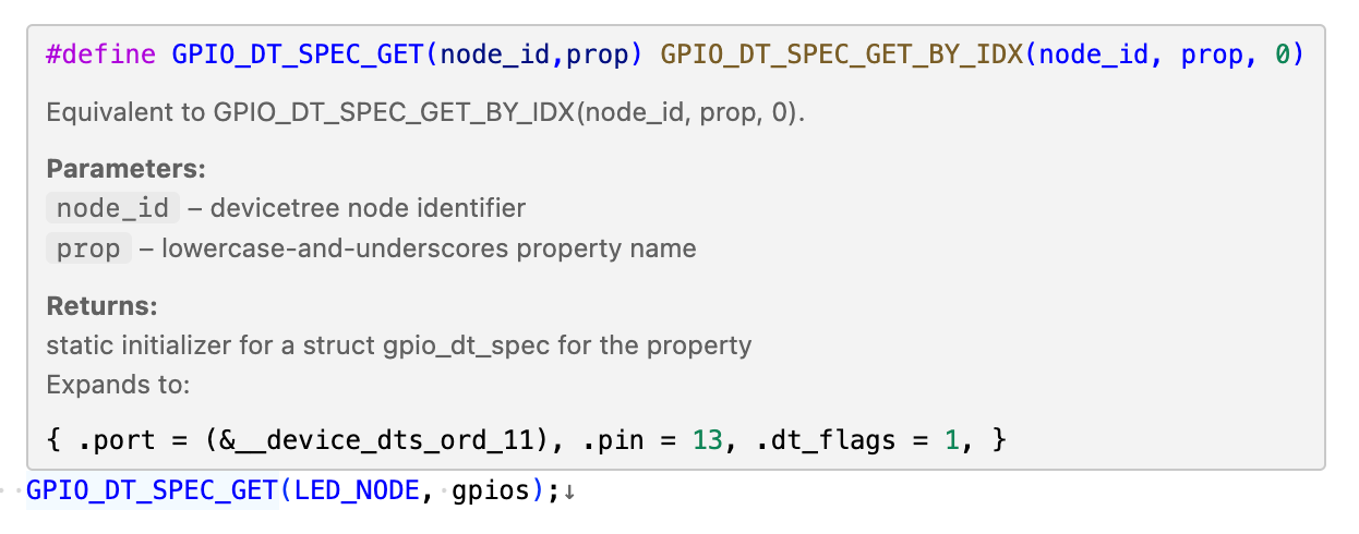
We could be satisfied with this resolution, but we’re not, are we? Aren’t you curious how we somehow get from a node identifier to this weird symbol with the ordinal 11? Well, I am so it’s time for some more macrobatics!
In the following snippet we replace referenced macros step by step without showing their definition, and thus - to some extent - perform the same expansion as the preprocessor. Since the steps are not exactly the same, however, we’re calling them “replacements” and not “expansions”:
// Original macro from zephyr/include/zephyr/device.h
#define DEVICE_DT_GET(node_id) (&DEVICE_DT_NAME_GET(node_id))

// 1st replacement: Given DEVICE_DT_NAME_GET = DEVICE_NAME_GET(Z_DEVICE_DT_DEV_ID(node_id))
#define DEVICE_DT_GET_1st(node_id) (&DEVICE_NAME_GET(Z_DEVICE_DT_DEV_ID(node_id)))

// 2nd replacement: Given DEVICE_NAME_GET = _CONCAT(__device_, dev_id)
#define DEVICE_DT_GET_2nd(node_id) (&_CONCAT(__device_, ,Z_DEVICE_DT_DEV_ID(node_id)))

// 3rd replacement: Z_DEVICE_DT_DEV_ID = _CONCAT(dts_ord_, DT_DEP_ORD(node_id))
#define DEVICE_DT_GET_3rd(node_id) (&_CONCAT(__device_, _CONCAT(dts_ord_, DT_DEP_ORD(node_id))))

// 4th replacement: DT_DEP_ORD = DT_CAT(node_id, _ORD)
#define DEVICE_DT_GET_4th(node_id) (&_CONCAT(__device_, _CONCAT(dts_ord_, DT_CAT(node_id, _ORD))))
Note: In case you’re wondering what the difference between
_CONCATandDT_CATis, experiment with token pasting. Hint: One of the macros simply pastes tokens, whereas the other one also expands the pasted token.
It’s easy enough to see how we end up with the prefix __device_dts_ord_, but it is not entirely clear yet how we get to the ordinal 11. For this, we still need to resolve DT_CAT(node_id, _ORD). Remembering that we already resolved our input parameter node_id to DT_N_S_soc_S_gpio_50000000, DT_CAT simply pastes the two tokens, and we end up with DT_N_S_soc_S_gpio_50000000_ORD. But what’s that? This is a macro that is again provided by Zephyr’s Devicetree generator:
$ grep DT_N_S_soc_S_gpio_50000000_ORD ../build/zephyr/include/generated/devicetree_generated.h
#define DT_N_S_soc_S_gpio_50000000_ORD 11
In simple words, Zephyr’s Devicetree generator assigns ordinals to device instances. This is a fundamental concept of Zephyr’s device API zephyr/include/zephyr/device.h, which is used to represent devices and their instances. Since this is a rather elaborate concept that goes beyond the scope of this article series, I’ll leave you with a link to Zephyr’s official documentation about the device driver model and instance-based APIs.
Note: You might ask yourself why we even need ordinals if Devicetree nodes are unique. One simple reason is that nodes can support multiple drivers, e.g., an IC might support SPI as well as I2C, and therefore two instances exist for a single node.
For now, it is enough to know that Zephyr creates symbols for each device instance in the Devicetree. In fact, in devicetree_generated.h we can find a list of the node ordering and thus ordinals of each instance at the very beginning of the file. Here, we find the ordinal 11 for the device of the GPIO node /soc/gpio@50000000, and also the ordinal 104 of the device for our second GPIO node /soc/gpio@50000300:
build/zephyr/include/generated/devicetree_generated.h
/*
 * Generated by gen_defines.py
 *
 * DTS input file:
 *   /path/to/build/zephyr/zephyr.dts.pre
 *
 * Directories with bindings:
 *   /opt/nordic/ncs/v3.2.1/nrf/dts/bindings, /path/to/dts/bindings, $ZEPHYR_BASE/dts/bindings
 *
 * Node dependency ordering (ordinal and path):
 *   0   /
 *   1   /aliases
 *   2   /analog-connector
 * --snip--
 *   11  /soc/gpio@50000000
 * --snip--
 *   104 /soc/gpio@50000300
 * --snip--
 */

// --snip--
#define DT_N_S_soc_S_gpio_50000300_ORD 104
// --snip--
#define DT_N_S_soc_S_gpio_50000000_ORD 11
Now we can finalize the macro expansion of DEVICE_DT_GET:
// given `DT_N_S_soc_S_gpio_50000000` for `node_id`:
// DT_CAT(node_id, _ORD)) resolves to `DT_N_S_soc_S_gpio_50000000_ORD`

#define DEVICE_DT_GET_4th(node_id) (&_CONCAT(__device_, _CONCAT(dts_ord_, DT_CAT(node_id, _ORD))))
#define DEVICE_DT_GET_x_1st()      (&_CONCAT(__device_, _CONCAT(dts_ord_, DT_N_S_soc_S_gpio_50000000_ORD)))
#define DEVICE_DT_GET_x_2nd()      (&_CONCAT(__device_, dts_ord_11))
#define DEVICE_DT_GET_x_3rd()      (&__device_dts_ord_11)
With this, we finally pieced together the complete assignment for our LED’s GPIO specification:
static const struct gpio_dt_spec led = GPIO_DT_SPEC_GET(LED_NODE, gpios);
// =  {
//    .port = (&__device_dts_ord_11),
//    .pin = 13 /* DT_N_S_leds_S_led_0_P_gpios_IDX_0_VAL_pin */,
//    .dt_flags = 1 /* DT_N_S_leds_S_led_0_P_gpios_IDX_0_VAL_flags */,
//  }
That’s all good and well, but where is this symbol __device_dts_ord_11 coming from? With all this macro magic, we can imagine that it is very unlikely that a search for __device within Zephyr’s codebase provides any valuable hint about the symbol’s location. Instead, we can use a much more reliable method: Let’s look for the symbol in the .map file:
$ grep -sw __device_dts_ord_11 ../build/zephyr/zephyr.map -A 1 -B 3
 .z_device_PRE_KERNEL_140_
    0x0000000000006550  0x30 zephyr/drivers/gpio/libdrivers__gpio.a(gpio_nrfx.c.obj)
    0x0000000000006550           __device_dts_ord_104
    0x0000000000006568           __device_dts_ord_11
 .z_device_PRE_KERNEL_155_
Note: Your
grepmileage may vary, I’ve just added-A 1and-B 3since I know that, in my application, the corresponding object and all the remaining instances are visible if I include one line after (-A 1) and three lines before (-B 3) the occurrence.
We found it! It seems to be declared in Nordic’s GPIO driver zephyr/drivers/gpio/gpio_nrfx.c.
Macrobatics: Declaring compatilble drivers and device object
I promised that we wouldn’t go into detail about Zephyr’s device driver model - and we won’t. In this section, we’ll only look at how the device instances are defined and how the connection with the nodes in the Devicetree is established.
The two responsible parts within gpio_nrfx.c for defining the instances are the following:
#define DT_DRV_COMPAT nordic_nrf_gpio
/* --snip-- the entire driver implementation */

#define GPIO_NRF_DEVICE(id)                 \
  /* --snip-- */                            \
  DEVICE_DT_INST_DEFINE(id, gpio_nrfx_init, \
      /* --snip-- */                        \
      &gpio_nrfx_drv_api_funcs);

DT_INST_FOREACH_STATUS_OKAY(GPIO_NRF_DEVICE)
The macro definition DT_DRV_COMPAT is placed at the beginning of the file. It is the device driver’s equivalent to the compatible property of Devicetree nodes and the same-named key in the Devicetree binding: It is defined to the “lowercase-and-underscore” form nordic_nrf_gpio of nordic,nrf-gpio.
At the end of the file, the device driver creates instances for all GPIO devices with the status property set to “okay” using the macro DT_INST_FOREACH_STATUS_OKAY. And that’s where somehow the “device objects” __device_dts_ord_104 and __device_dts_ord_11 of the corresponding GPIO nodes are created, pretty likely through DEVICE_DT_INST_DEFINE.
Let’s dissect these macros one by one, starting with DT_INST_FOREACH_STATUS_OKAY, which is more concise but also more complex:
#define DT_INST_FOREACH_STATUS_OKAY(fn)                       \
  COND_CODE_1(DT_HAS_COMPAT_STATUS_OKAY(DT_DRV_COMPAT),       \
    (UTIL_CAT(DT_FOREACH_OKAY_INST_, DT_DRV_COMPAT)(fn)),     \
    ()                                                        \
  )
For the expansion of COND_CODE_1 we rely on the docs, which state that this macro “insert[s] code depending on whether _flag expands to 1 or not.”. The first parameter is the _flag, the second parameter is the code in case _flag expands to 1, and finally, the third parameter is the code that is used in case the _flag is not 1 or undefined.
To get to the flag, we need to check DT_HAS_COMPAT_STATUS_OKAY(DT_DRV_COMPAT):
#define DT_HAS_COMPAT_STATUS_OKAY(compat) \
  IS_ENABLED(DT_CAT(DT_COMPAT_HAS_OKAY_, compat))
We’ve seen the IS_ENABLED macro already: It is a more intricate macro that allows evaluating tokens even if they are not even defined. Since we know that in our case compat is nordic_nrf_gpio, we’re looking for a macro DT_COMPAT_HAS_OKAY_nordic_nrf_gpio, which, as usual, we can find in devicetree_generated.h:
grep -w DT_COMPAT_HAS_OKAY_nordic_nrf_gpio ../build/zephyr/include/generated/devicetree_generated.h
#define DT_COMPAT_HAS_OKAY_nordic_nrf_gpio 1
Zephyr’s Devicetree generator creates a lot more information than just macros for the property values of our Devicetree nodes! Here, we see that the generator also provides macros indicating whether it encountered some nodes that claim compatibility with “nordic,nrf-gpio”. If it doesn’t encounter any such node, it won’t create the corresponding macros and we’d know that the content of any driver compatible with “nordic,nrf-gpio” is unused and can thus be discarded. Pretty neat!
The Devicetree generator does this for each and every driver and node. This allows heavy optimizations in the codebase as we’ve seen above.
Now we found out that our driver is used, and thus the second parameter of COND_CODE_1 is expanded. We’ve already seen that UTIL_CAT concatenates and expands the provided macros, which are DT_FOREACH_OKAY_INST_ and our DT_DRV_COMPAT macro, which expands to nordic_nrf_gpio. Thus, we’re now looking for a macro DT_FOREACH_OKAY_INST_nordic_nrf_gpio:
grep -w DT_FOREACH_OKAY_INST_nordic_nrf_gpio ../build/zephyr/include/generated/devicetree_generated.h
#define DT_FOREACH_OKAY_INST_nordic_nrf_gpio(fn) fn(0) fn(1)
Also here Zephyr’s Devicetree generator creates another useful macro based on the number of devices in the Devicetree claiming compatibility with the nordic,nrf-gpio device driver. For each device it encounters it adds a fn(n) to the macro, where n is the instance number of the device, one for each of our GPIO nodes. Given this macro, we now know the complete expansion of the DT_INST_FOREACH_STATUS_OKAY macro:
// `DT_INST_FOREACH_STATUS_OKAY(GPIO_NRF_DEVICE)`
// given DT_DRV_COMPAT = nordic_nrf_gpio
// expands to:
GPIO_NRF_DEVICE(0) GPIO_NRF_DEVICE(1)
The above macros are expanded for the corresponding device instance number, but we still don’t know how to associate the instance number with the ordinals, which are 11 and 104 for our GPIO devices. So far, we can only establish a connection to the nodes /soc/gpio@50000000 and /soc/gpio@50000300 via the ordinals.
This leads us to the expansion of DEVICE_DT_INST_DEFINE used by GPIO_NRF_DEVICE:
#define GPIO_NRF_DEVICE(id)                 \
  /* --snip-- */                            \
  DEVICE_DT_INST_DEFINE(id, gpio_nrfx_init, \
      /* --snip-- */                        \
      &gpio_nrfx_drv_api_funcs);

// 1st replacement:
// DEVICE_DT_INST_DEFINE(inst, ...) =
//   DEVICE_DT_DEFINE(DT_DRV_INST(inst), __VA_ARGS__)
#define GPIO_NRF_DEVICE_1st(id)                     \
  /* --snip-- */                                    \
  DEVICE_DT_DEFINE(DT_DRV_INST(id), gpio_nrfx_init, \
      /* --snip-- */                                \
      &gpio_nrfx_drv_api_funcs);
The documentation of DT_DRV_INST states that it is used to get the “node identifier for an instance of a DT_DRV_COMPAT compatible”. That’s exactly what we’d expect, but we want to know how this is done: How do we match a node (identifier) to a device instance number? Looks like we’ll have to do a quick macro expansion for DT_DRV_INST as well:
// Expansion of DT_DRV_INST, given
// DT_INST(inst, compat) = UTIL_CAT(DT_N_INST, DT_DASH(inst, compat))
// and DT_DASH pastes underscores before and between the arguments.
#define DT_DRV_INST_1st(inst)  DT_INST(inst, DT_DRV_COMPAT)
#define DT_DRV_INST_2nd(inst)  UTIL_CAT(DT_N_INST, DT_DASH(inst, DT_DRV_COMPAT))
#define DT_DRV_INST_3rd(inst)  UTIL_CAT(DT_N_INST, _ ## inst ## DT_DRV_COMPAT)

// Given:
// - DT_DRV_COMPAT = nordic_nrf_gpio
// - inst = 0 (and analog for 1, from the expansion of DT_INST_FOREACH_STATUS_OKAY)
#define DT_DRV_INST_0_1st  UTIL_CAT(DT_N_INST, DT_DASH(0, nordic_nrf_gpio))
#define DT_DRV_INST_0_2nd  UTIL_CAT(DT_N_INST, _0_nordic_nrf_gpio)
#define DT_DRV_INST_0_3rd  DT_N_INST_0_nordic_nrf_gpio
// and  DT_DRV_INST_1_3rd  DT_N_INST_1_nordic_nrf_gpio  ... for inst = 1
$ grep -w DT_N_INST_0_nordic_nrf_gpio ../build/zephyr/include/generated/devicetree_generated.h
#define DT_N_INST_0_nordic_nrf_gpio DT_N_S_soc_S_gpio_50000000
$ grep -w DT_N_INST_1_nordic_nrf_gpio ../build/zephyr/include/generated/devicetree_generated.h
#define DT_N_INST_1_nordic_nrf_gpio DT_N_S_soc_S_gpio_50000300
Yet again Zephyr’s Devicetree generator provides the necessary macros to map the instance number inst to the matching node that claims compatibility with a given device driver:
-
/soc/gpio@50000000is instance 0, and -
/soc/gpio@50000300is instance 1 of the drivernordic,nrf-gpio.
This is it! We now have the connection from our instance number to node identifier and thus the Devicetree node. We’ve already seen how we can get from the node identifier to the “device object’s” name, and can therefore apply that knowledge to declare the symbol.
Through several expansions, the device macro DEVICE_DT_DEFINE effectively does exactly that: It declares a global constant using the name __device_dts_ord_<N>, where N is the ordinal it obtains using the node identifier of the corresponding instance. The following is an oversimplified definition for the macro DEVICE_DT_DEFINE:
// Simplified definition of DEVICE_DT_DEFINE for the device object:
#define DEVICE_DT_DEFINE_simplified(node_id, ...)                     \
  const struct device DEVICE_NAME_GET(Z_DEVICE_DT_DEV_ID(node_id)) =  \
    Z_DEVICE_INIT(/* --snip-- */)

// Remember the expansion of DEVICE_NAME_GET(Z_DEVICE_DT_DEV_ID(node_id)
// in the expansion for DEVICE_DT_GET that we've seen before.

// For node_id = DT_N_S_soc_S_gpio_50000000 ->
// const struct device __device_dts_ord_11 = ...
// For node_id = DT_N_S_soc_S_gpio_50000300 ->
// const struct device __device_dts_ord_104 = ...
In practice, Zephyr also creates other symbols that are used to populate the device object. This device object contains, e.g., a function table for the entire GPIO API, such that a call to a gpio function leads to the correct call of the vendor’s function. E.g., a call to gpio_pin_toggle_dt for a GPIO that is compatible with nordic,nrf-gpio eventually leads to a call to gpio_nrfx_port_toggle_bits.
For details, however, you’ll need to refer to Zephyr’s official documentation about the device driver model and instance-based APIs, or watch the tutorial “Mastering Zephyr Driver Development” by Gerard Marull Paretas from the Zephyr Development Summit 2022.
There’s also a blog post on this Interrupt blog about building drivers on Zephyr.
Summary
We now not only know how the GPIO subsystem uses the macros from devicetree.h to get the specifiers for gpio properties of type phandle-array, but we also know what the device objects are and how they’re resolved:
static const struct gpio_dt_spec led = GPIO_DT_SPEC_GET(LED_NODE, gpios);
// =  {
//    .port = (&__device_dts_ord_11),
//    .pin = 13 /* DT_N_S_leds_S_led_0_P_gpios_IDX_0_VAL_pin */,
//    .dt_flags = 1 /* DT_N_S_leds_S_led_0_P_gpios_IDX_0_VAL_flags */,
//  }
Zephyr’s Devicetree generator provides much more than just macros for accessing property values in the Devicetree. It also creates the necessary macros to associate driver instances with nodes, and to create the corresponding instances in the device driver itself. And then some …
The status property
One important property that we’ve touched already is the status property. While our LED node has no such property, the referenced GPIO node in its gpios property does. The nodes are first defined in the MCU’s DTS file with the status property set to "disabled":
zephyr/dts/arm/nordic/nrf52840.dtsi
/ {
  soc {
    gpio0: gpio@50000000 { /* --snip-- */ status = "disabled"; port = <0>; };
    gpio1: gpio@50000300 { /* --snip-- */ status = "disabled"; port = <1>; };
  };
};
In the nRF52840 development kit’s DTS file, the status property is overwritten with "okay":
zephyr/boards/nordic/nrf52840dk/nrf52840dk_nrf52840.dts
&gpio0 { status = "okay"; };
&gpio1 { status = "okay"; };
Zephyr’s introduction to Devicetree explains the status property in a dedicated section for important Devicetree properties as follows:
“A node is considered enabled if its
statusproperty is either"okay"or not defined (i.e., does not exist in the Devicetree source). Nodes withstatus"disabled"are explicitly disabled. […] Devicetree nodes which correspond to physical devices must be enabled for the correspondingstructdevice in the Zephyr driver model to be allocated and initialized.”
This matches with what we’ve seen for the DT_INST_FOREACH_STATUS_OKAY macro in gpio_nrfx.c: Instances are only created for each node with the status set to "okay". We can disable the node by setting the status to "disabled" in our application’s board overlay file:
&gpio0 {
    status = "disabled";
};
Trying to recompile the project leads to the linker error that we’ve seen in the documentation of DEVICE_NAME_GET:
/opt/nordic/ncs/v3.2.1/zephyr/include/zephyr/device.h:84:41: error:
'__device_dts_ord_11' undeclared here (not in a function);
did you mean '__device_dts_ord_15'?
   84 | #define DEVICE_NAME_GET(dev_id) _CONCAT(__device_, dev_id)
      |                                         ^~~~~~~~~
The matching device object has not been allocated in gpio_nrfx.c and thus the linker can’t resolve the symbol __device_dts_ord_11. For demonstration purposes (this is not typically done in an application) we could transform this into a compiler error by using the devicetree.h API as follows:
#if DT_NODE_HAS_STATUS(DT_PHANDLE(LED_NODE, gpios), okay)
static const struct gpio_dt_spec led = GPIO_DT_SPEC_GET(LED_NODE, gpios);
#else
#error "The status of the GPIO referenced by the LED node is not 'okay'"
#endif
Discard the changes to the board’s overlay and remove the conditional compilation in the sources. The documentation also mentions, that the status property is implicitly added with the value "okay" for nodes that do not define the property in the Devicetree. As we can see in the merged zephyr.dts file in the build folder, our /leds/led_0 node doesn’t have the status property:
build/zephyr/zephyr.dts
/ {
  leds {
    compatible = "gpio-leds";
    led0: led_0 {
      gpios = < &gpio0 0xd 0x1 >;
      label = "Green LED 0";
    };
  };
};
Instead of looking into devicetree_generated.h, we can also check that the node is indeed implicitly assigned the status with the value "okay" using the following compile time switch and macros from devicetree.h:
#if !DT_NODE_HAS_STATUS(LED_NODE, okay)
#error "LED node status is not okay." /* `status` is added implicitly. */
#endif
Rebuilding the application works without any warnings or errors and the LED continues blinking happily. You’ll find such conditional compilation switches in many of Zephyr’s source files. How the status property is used varies between the corresponding subsystems.
What’s the use of the status, then? You can and should use status to disable all nodes that you don’t need. This typically leads to a (slight) reduction of code size but is especially important for low-power applications to reduce power consumption by disabling unused peripherals.
Note: In case you’re wondering what the difference between the
statusproperty and theis_ready_dtfunction call is - you’re not alone, so let’s clarify this briefly. Thestatusproperty is used to remove instances altogether, whereas theis_ready_dtensures that the driver is ready to be used. You can’t callis_ready_dtwith a specification for a disabled node - as we’ve seen, the compilation or linking fails entirely for disabled nodes.
Note: The dreaded
'__device_dts_ord_<n>' undeclaredlinker error can now also be investigated using Zephyr’s devicetree doctor. This devicetree doctor is a static analysis tool and can be run usingwest build <your arguments> -- -DZEPHYR_SCA_VARIANT=dtdoctor.
Intermezzo: Power profiling
Let’s apply what we’ve just learned and observe the MCU’s current consumption with and without disabling unused nodes. To do that, I’ll be using Nordic’s Power Profiler Kit. You can, of course, use any clamp meter or other measurement hardware to verify the current consumption.
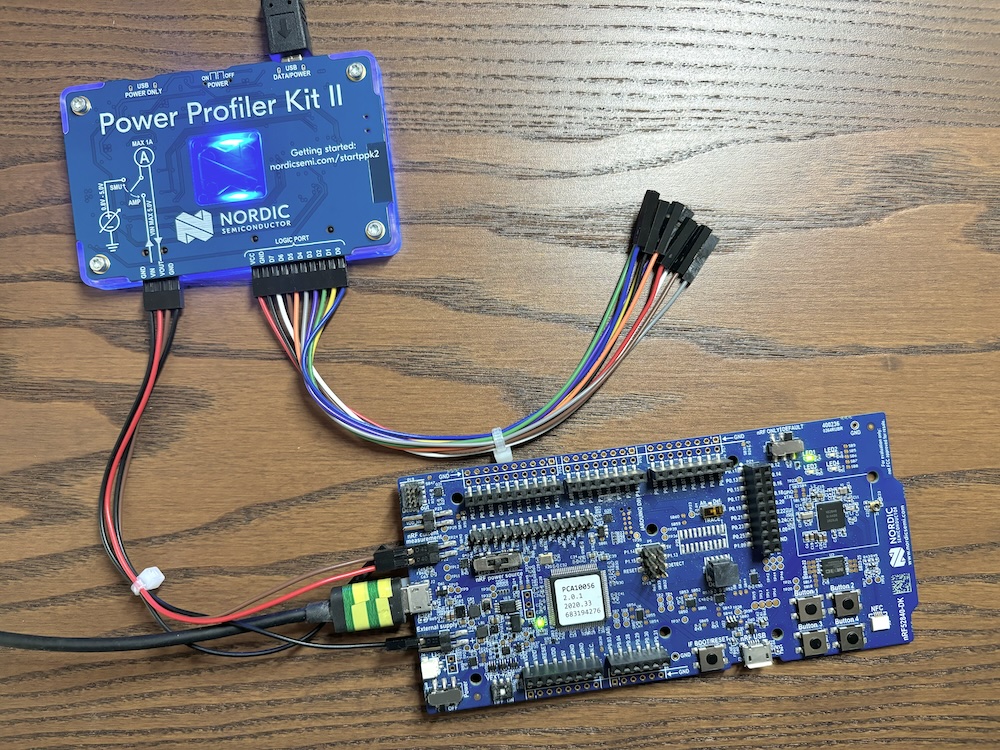
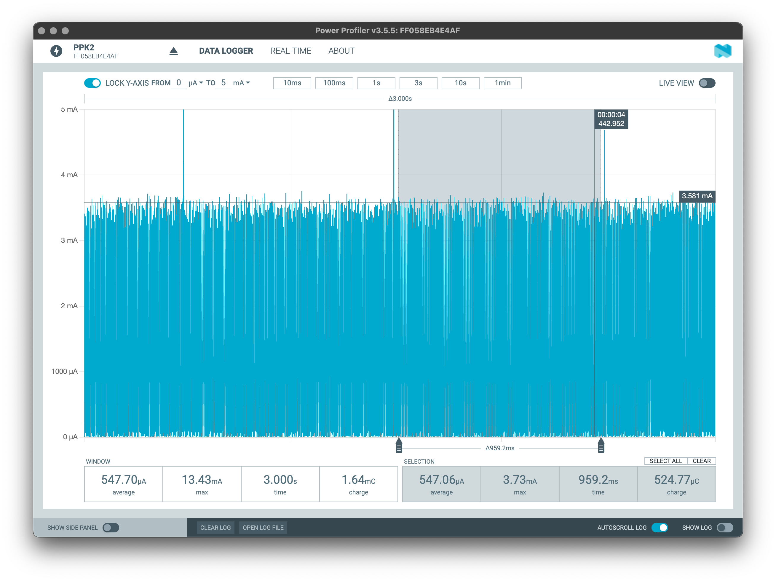
Without disabling unused nodes, I’m observing a current consumption in the application’s sleep cycles of around 550 uA. The screenshot below shows the measurement for an interval of 3 seconds, where the y-axis measures the current consumption truncated to a range of 0 .. 5 mA. You should still be able to make out the three peaks in the current consumption where the MCU wakes up to toggle the LED.
How can we find out which nodes to disable?
Zephyr’s board DTS files typically enable plenty of nodes, mostly for you to be able to run the samples without having to use an overlay to enable the required nodes. For a custom board, this might not be the case, meaning nodes could be disabled by default and you might have to enable nodes before using them. In the end, you should be well aware of the peripherals and thus nodes that you need, and should thus simply know which nodes can be disabled.
In case of doubt another good location to look for a node’s status is the zephyr.dts in the build directory. I’ve picked the following nodes from there and disabled them in the board’s overlay:
boards/nrf52840dk_nrf52840.overlay
&adc {status = "disabled"; };
&i2c0 {status = "disabled"; };
&i2c1 {status = "disabled"; };
&pwm0 {status = "disabled"; };
&spi0 {status = "disabled"; };
&spi1 {status = "disabled"; };
&spi3 {status = "disabled"; };
&usbd {status = "disabled"; };
&nfct {status = "disabled"; };
&temp {status = "disabled"; };
&radio {status = "disabled"; };
&uart0 {status = "disabled"; };
&uart1 {status = "disabled"; };
Note: We’re also disabling
uart0and therefore the/chosennode for our console output - the boot banner*** Booting Zephyr OS build v3.3.99-ncs1 ***will no longer be output.
After rebuilding and flashing the application, I can perform the same measurement again and I indeed got a very different result, as you can see in the below screenshot:
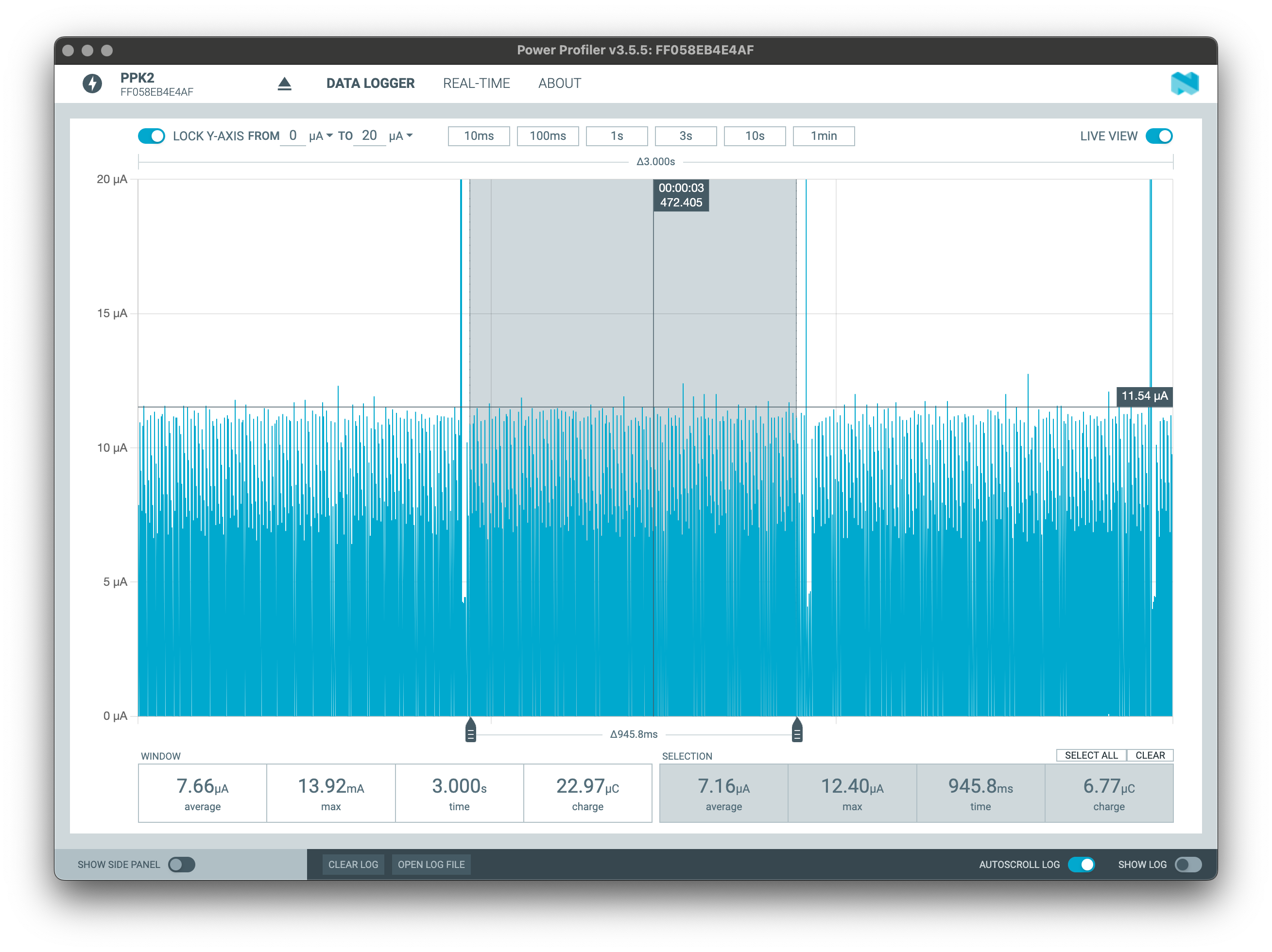
Notice that the scale of the y-axis changed from 0 .. 5 mA to 0 .. 20 uA, that’s a factor 250 smaller! This is also visible in the MCU’s current consumption in the sleep phase, which dropped from 550 uA to an average of 7 uA.
It is quite convenient and easy enough to disable unused peripherals. If you think that power management is Zephyr is as simple as that, however, I’ll have to disappoint you: This is really just a way to disable peripherals that are not used at all. If we’d, e.g., need the UART while the device is not in sleep mode, we’re looking at an entirely different mechanism. We’ll only scratch the surface of power management in Zephyr when we have a look at pin control, but for details, you’ll need to dive into the official documentation.
Comparing the memory usage of the build with and without optimized node status, we can also see a slight gain in the flash memory consumption:
# west build with all nodes "okay"
Memory region     Used Size  Region Size  %age Used
       FLASH:       27808 B         1 MB      2.65%
         RAM:        7552 B       256 KB      2.88%
    IDT_LIST:          0 GB         2 KB      0.00%
# west build with optimized node status
Memory region     Used Size  Region Size  %age Used
       FLASH:       25352 B         1 MB      2.42%
         RAM:        7552 B       256 KB      2.88%
    IDT_LIST:          0 GB         2 KB      0.00%
Device driver function calls
Even though we still won’t write an instance-based device driver in this article series it is worth quickly (and this time I mean really quickly) reviewing how Zephyr’s API function calls map to the function tables provided by the device drivers.
Let’s first have a look at an overly simplified Devicetree driver function call tree for gpio_pin_configure_dt, which looks approximately as follows:
gpio_pin_configure_dt(
  │     spec, extra_flags)
  └── gpio_pin_configure(
        │     spec->port, spec->pin, spec->dt_flags | extra_flags)
        └── z_impl_gpio_pin_configure(
              │     spec->port, spec->pin, spec->dt_flags | extra_flags)
              └── spec->port->api->pin_configure(
                        spec->port, spec->pin, flags)
A call to gpio_pin_configure_dt thus maps to the function call spec->port->api->pin_configure. When we dissected the GPIO pin information type, we’ve already seen that spec->port is assigned the device object __device_dts_ord_<N>. Knowing already that our device object is created in zephyr/drivers/gpio/gpio_nrfx.c, we can immediately see that the API function table is the last parameter passed to the macro DEVICE_DT_INST_DEFINE:
zephyr/drivers/gpio/gpio_nrfx.c
static const struct gpio_driver_api gpio_nrfx_drv_api_funcs = {
  .pin_configure = gpio_nrfx_pin_configure,
  // --snip--
};

// --snip--
#define GPIO_NRF_DEVICE(id)                 \
  /* --snip-- */                            \
  DEVICE_DT_INST_DEFINE(id, gpio_nrfx_init, \
      /* --snip-- */                        \
      &gpio_nrfx_drv_api_funcs);

D
0 Comments
Log in to join the conversation.No comments yet. Be the first to share your thoughts.