
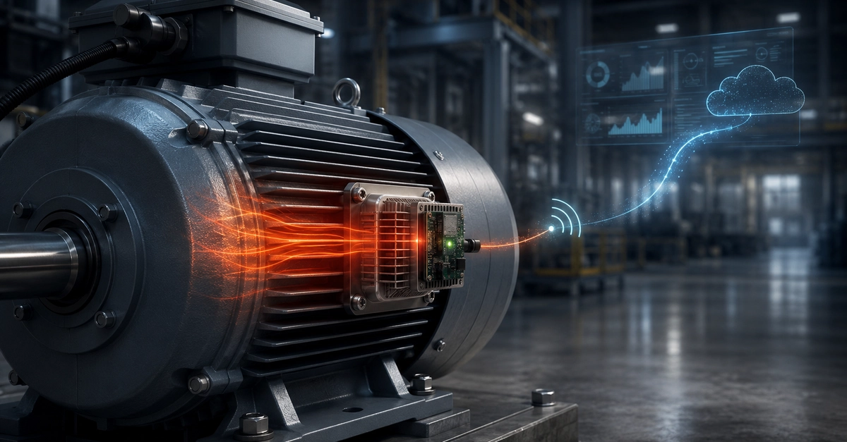
Industrial motors continuously reject energy as heat. Under the right conditions, a small part of that heat can power the sensor used to monitor the motor itself. This does not mean unlimited energy or zero engineering effort. It means designing an embedded node that measures, processes and transmits only when the available energy can support a complete operating cycle.
The idea is appealing in industrial IoT monitoring, where wiring every sensor may be expensive and replacing batteries across dozens or hundreds of nodes becomes an operational burden. The benefit is greatest on hard-to-reach assets, sealed enclosures and machinery that cannot be stopped frequently.
This article reviews a 2026 Sensors study in which a thermoelectric generator was installed on a 0.25 kW industrial gearmotor. The harvested energy powered a microcontroller and a LoRa transceiver. In the complete test, the system completed 41 wireless transmissions without an electrochemical battery while maintaining a positive energy balance.
Key findings
- The TEG operated at a stabilized temperature difference of about 4.8-5.2 °C.
- During the end-to-end test, the node harvested 6.17 J and consumed 6.05 J in 9,612 seconds.
- The result demonstrates a duty-cycled LoRa node, not a maintenance-free sensor for every industrial motor.
The challenge is not producing voltage, but closing the energy budget
Energy harvesting can recover small amounts of energy from light, vibration, electromagnetic fields or temperature differences. The presence of an energy source, however, does not automatically make a sensor autonomous.
A practical design must account for conversion losses, regulator quiescent current, storage leakage, microcontroller sleep current, sensor acquisition and the short but demanding peaks caused by radio transmission. A few continuous microamps can be enough to break the budget when the harvested power is measured in microwatts or milliwatts.
The useful question is therefore not simply “how much voltage does the generator produce?” but “how much energy remains after every loss, and how often can the node safely acquire and transmit?”
How a thermoelectric generator works
A thermoelectric generator, usually abbreviated to TEG, uses the Seebeck effect. A voltage appears across the module when its two faces are at different temperatures.
As a first approximation, the open-circuit voltage rises with the temperature difference actually present across the module:
V_OC ≈ α × ΔT
Here V_OC is open-circuit voltage, α is the module’s effective Seebeck coefficient and ΔT is the real temperature difference between the hot and cold sides.
The key parameter is not the motor’s absolute temperature. It is the gradient applied directly to the TEG. If both faces approach the same temperature, electrical output falls even when the machine housing is hot.
Mechanical contact, surface flatness, interface material, heat-sink design, airflow and parasitic thermal paths all determine how much of the available heat can become useful electrical energy. At low ΔT, even a small loss at an interface can decide whether the design is viable.
The 0.25 kW industrial motor test
The prototype described in the paper was installed on a 0.25 kW Bosch Rexroth gearmotor used in a Smart Factory demonstrator at VSB-Technical University of Ostrava. Before installation, the researchers used thermal imaging to map the housing. Surface temperature ranged roughly from 35 to 60 °C, but the distribution was not uniform.
The selected TEG was a Marlow RC12-8-01LS, measuring 40 by 44.7 mm and 3.51 mm thick. Because the TEG is flat and the motor housing is curved, the team machined a custom aluminium adapter. A heat sink was mounted on the cold side, and a small duct directed part of the motor fan airflow through the fins.
Thermal paste was used between the interfaces to reduce microscopic voids and contact resistance.
Thermal chain in the prototype
| Element | Role in the thermal budget |
|---|---|
| Motor housing | Heat source; surface temperature alone does not define the available electrical power. |
| Aluminium adapter | Matches the curved housing to the flat TEG and improves mechanical contact. |
| Marlow RC12-8-01LS TEG | Converts the temperature difference between its faces into electrical voltage. |
| Heat sink and fan airflow | Remove heat from the cold side and preserve a useful ΔT. |
Why cooling the cold side matters
A TEG does not generate useful energy merely because it is heated. A thermal path must also remove heat from the cold side. In this prototype, the motor fan served two roles: cooling the motor as intended and forcing air through the additional heat sink.
That arrangement stabilized the TEG temperature difference between approximately 4.8 and 5.2 °C during steady operation. Including the warm-up and other transients, the average gradient over the full experiment was lower.
This is why “five degrees are enough” is the wrong takeaway. The product must create and preserve those five degrees across the TEG itself, including unfavourable conditions such as a hot ambient, reduced motor load, a dirty heat sink, changing airflow and ageing thermal interfaces.
From tens of millivolts to a usable supply
The TEG voltage was in the tens-of-millivolts range, far too low to directly power a microcontroller or radio. The study therefore used a power chain designed for extremely low-voltage sources:
TEG → LTC3109 → storage capacitor → TPS62840 → KL25Z4 microcontroller and SX1261 LoRa transceiver
Power path and node load
| Stage | Component | Purpose |
|---|---|---|
| Harvesting source | TEG | Provides millivolt-level voltage from the thermal gradient. |
| Start-up and harvesting | LTC3109 | Steps up very low input voltage and manages storage charging. |
| Storage | 20 mF capacitor | Accumulates energy slowly to cover acquisition and radio peaks. |
| Regulation | TPS62840 | Provides a regulated supply with very low quiescent current. |
| Processing and radio | KL25Z4 + SX1261 | Acquire, process and transmit the LoRa payload when sufficient energy is available. |
The first stage was an Analog Devices LTC3109, an ultralow-voltage step-up converter and power manager. Its documentation specifies cold start from roughly 30 mV under appropriate transformer, source-impedance and operating conditions.
Harvested energy was stored in a 20 mF capacitor. Downstream, a Texas Instruments TPS62840 buck converter was used, with a specified typical quiescent current of 60 nA. Control was handled by an NXP KL25Z4 Cortex-M0+ microcontroller, while the radio was a Semtech SX1261 LoRa transceiver.
What “batteryless” really means
In this experiment, batteryless means that the node uses no primary or rechargeable electrochemical battery. It does not mean the node has no energy storage at all.
The capacitor collects the TEG’s small output over time and releases it during short, high-current events. A radio transmission requires more instantaneous power than the generator can deliver directly at every moment.
For a real product, choosing between a capacitor, supercapacitor or hybrid store requires evaluating capacitance, leakage, temperature behaviour, peak current, life, cycling and cold-start time.
Firmware schedules work around available energy
An always-powered device can sample and transmit on a fixed timer. With harvested energy, that approach can cause brownouts when supply falls. The experimental firmware continuously monitored capacitor voltage and transmitted only after it exceeded 2 V. After a successful transmission, the node slept for 20 seconds while the TEG replenished part of the used energy.
Message timing was therefore not a fixed timer setting. It emerged from thermal power, conversion efficiency and the energy cost of the cycle. This is an energy-aware duty-cycling approach: available energy becomes a firmware state variable that controls sampling, processing and radio activity.
A production implementation should also include threshold hysteresis, brownout detection, a watchdog, safe restart behaviour, atomic writes to non-volatile memory, controlled peripheral shutdown and adaptive acquisition intervals. These are core firmware design concerns, not optional refinements.
LoRa configuration used in the test
Radio configuration in the experiment
| Parameter | Setting |
|---|---|
| Band | EU868 |
| Modulation | LoRa |
| Spreading factor | SF12 |
| Bandwidth | 125 kHz |
| Preamble | 8 symbols |
| Payload | 32 bytes |
SF12 increases time on air relative to lower spreading factors, making this a comparatively demanding radio configuration. It is not automatically the best setting for every installation. A product design must consider distance, obstacles, antenna, link budget, regional constraints, retransmissions and the energy cost of the whole message.
Measured electrical output from the TEG
During resistive-load characterization, TEG output rose as the motor warmed. The reported maximum voltage was 89.6 mV, the average voltage 64.2 mV, maximum power 5.07 mW and average power 3.16 mW.
TEG electrical power measured with a resistive load
| ΔT across the TEG | Measured power |
|---|---|
| 0.5 °C | 6.26 µW |
| 1 °C | 69.25 µW |
| 2 °C | 193.82 µW |
| 3 °C | 1.26 mW |
| 4 °C | 2.80 mW |
| 5 °C | 4.72 mW |
The jump from 3 to 5 °C was not marginal: measured power rose from about 1.26 to 4.72 mW. Positioning, heat-sink design, contact pressure and interface material can therefore change the viable reporting interval dramatically.
The complete microcontroller and LoRa test
The most relevant result is the complete-node test, not the TEG characterization alone.
Measured end-to-end energy balance
| Metric | Value |
|---|---|
| Harvested energy | 6.17 J |
| Consumed energy | 6.05 J |
| Energy margin | 0.12 J |
| Completed LoRa transmissions | 41 |
P_harv,avg = 6.17 J ÷ 9,612 s ≈ 0.64 mW
During the stable part of the test, many intervals between transmissions were roughly 170 to 220 seconds, with a median near 200 seconds. Dividing the full test time by all 41 messages, including start-up and transients, gives an average interval of about 234 seconds or 3.9 minutes.
All scheduled uplinks in that measurement window were received. The authors note that the evaluation was at packet level, not a dedicated RF bit-error-rate measurement. It is a positive result for that duration and those conditions, not a general reliability guarantee.
Why TEG power and system power are different
The TEG’s 3.16 mW average from resistive-load characterization and the approximately 0.64 mW average inferred from the complete node’s harvested energy are not directly comparable measurements.
The former is a generator characterization under a matched resistive load. The latter includes DC/DC conversion, storage, leakage, quiescent current, the microcontroller, radio bursts, start-up and changing thermal conditions. Dividing one value by the other would not produce a valid end-to-end efficiency. That requires synchronized measurements at defined points in the power path.
The 72-hour thermal test
The researchers also ran a 72.23-hour test with a 1 F capacitor to study thermal stability and storage over time. After the initial transient, the median gradient was 4.918 °C, with an interquartile range of 0.043 °C. Median TEG voltage was about 120.2 mV.
The capacitor reached 5.161 V, corresponding to roughly 13.319 J of stored energy.
E_C = 1/2 × C × (V_high² − V_low²)
With C = 1 F and V_low close to zero, the equation gives about 13.32 J. It is useful when estimating the energy actually available between two voltage thresholds.
The 72-hour test shows good thermal and electrical stability, but it is not a 72-hour end-to-end LoRa validation. Complete packet-success logs were not available for that data set. The authors project roughly 1,110 possible transmissions from the shorter test interval; that is an analytical projection, not 1,110 directly verified uplinks.
Measured performance versus estimated performance
The paper also estimates the reporting interval available at different gradients:
Transmission interval estimated by the authors
| ΔT across the TEG | Estimated interval | Data type |
|---|---|---|
| 0.5 °C | 1,976 minutes | Estimate |
| 1 °C | 179 minutes | Estimate |
| 2 °C | 64 minutes | Estimate |
| 3 °C | 10 minutes | Estimate |
| 4 °C | 4.4 minutes | Estimate |
| 4.5 °C | 3.3 minutes | Estimate |
| 5 °C | 2.6 minutes | Estimate |
Those values are not complete system tests at every temperature. They are extrapolations based on measured power and an experimentally verified operating point. They are useful for first-pass sizing, but not guaranteed field performance.
What this experiment proves, and what it does not
The work demonstrates that about 5 °C across a correctly installed TEG can power a small, duty-cycled embedded node; that a suitable power-management chain can turn tens of millivolts into a useful supply; and that energy-aware firmware can adapt reporting to actual available energy.
It does not make the prototype a production-ready industrial product. The complete node was verified for only a few hours, on one motor type, in relatively stable conditions. The study did not validate multi-year TEG and capacitor life, thermal-paste ageing, vibration resistance, repeated thermal cycling or a mechanical interface suitable for many motor geometries.
The 0.12 J margin is enough to demonstrate feasibility in the reported conditions, but a product needs allowance for ambient variation, motor load changes, restarts, radio retries, worst-case tolerances, additional sensors, leakage and ageing.
Predictive maintenance is a possible use case, not a validated outcome
The study presents predictive maintenance as a potential application, but its experimental validation concerns node power and wireless communication. It does not demonstrate a classifier for damaged bearings, fault detection or remaining-useful-life prediction.
A dependable condition-monitoring system also needs the right sensor, a suitable acquisition strategy, useful local features, data from normal and faulty conditions, and validation against false positives and false negatives. Energy harvesting can power the measurement platform; it does not replace the work of turning measurements into a trustworthy diagnosis.
Realistic applications
With average available power in the hundreds-of-microwatts range, this architecture fits short active periods followed by long sleep periods. Plausible applications include periodic temperature measurement, run-hour counting, sporadic event detection, aggregate statistics, low-rate alarms and monitoring hard-to-wire machinery.
For vibration monitoring, a practical approach is to wake an accelerometer periodically, capture a short window, calculate features such as RMS, peak, crest factor or selected spectral-band energy, and transmit only those features. Edge processing reduces radio energy by avoiding continuous waveform transfer.
Continuous high-frequency acquisition, frequent raw-waveform transmission, always-on Linux processing, video or large payloads are not realistic with the demonstrated budget.
How to evaluate a proof of concept on a real machine
- Map the thermal source. Measure housing and ambient temperature, ΔT directly across the TEG, warm-up time, different loads, start-stop behaviour and seasonal variation.
- Build the complete energy model. Include converter cold start and efficiency, storage leakage, regulator and MCU sleep current, sensor energy, radio energy, timeouts and retries.
- Engineer the mechanical and thermal interface. Validate contact pressure, curvature, interface material, heat sink, vibration, contaminants, cable protection and maintainability.
- Design for intermittent energy. Handle brownouts, watchdog recovery, threshold hysteresis, atomic non-volatile state, controlled peripheral shutdown and adaptive operation.
- Validate over time. A proof of concept proves a direction. A product needs representative duration, temperature, vibration and environmental tests.
P_harv,avg > (E_cycle ÷ T_cycle) + P_sleep
This equation does not replace measurement. It makes the design constraint explicit: average harvested power must exceed the mean cost of operating cycles plus continuous sleep consumption.
Conclusion
The Sensors study is valuable because it integrates the TEG, power management, storage, microcontroller, firmware and LoRa communication, then measures a positive energy balance. It shows that waste heat from a small motor can sustain a duty-cycled wireless node when the whole system is designed around a very small power budget.
It does not mean that any hot motor can automatically power a maintenance-free sensor. Feasibility depends on the real gradient, mounting, heat rejection, machine operating profile, load consumption and long-term stability. Thermoelectric energy harvesting does not remove power-design work; it makes thermal, mechanical, electronics and firmware engineering more tightly coupled.
Technical references
[1] K. Bancik, J. Konecny, M. Stankus, R. Hercik, J. Koziorek, V. Markevičius, D. Andriukaitis and M. Prauzek, Batteryless IoT Sensing Using Thermoelectric Energy Harvesting from Industrial Motor Waste Heat, Sensors, 26(5), 1644, 2026. DOI: 10.3390/s26051644.
[2] Analog Devices, LTC3109: Auto-Polarity, Ultralow Voltage Step-Up Converter and Power Manager.
[3] Texas Instruments, TPS62840: 1.8-V to 6.5-V, 750-mA, 60-nA IQ Step-Down Converter.
[4] M. Prauzek, Batteryless IoT Sensing Using Thermoelectric Energy Harvesting from Industrial Motor Waste Heat, measurement data set and processing scripts, Zenodo. DOI: 10.5281/zenodo.17670801.
Considering a batteryless wireless sensor for an industrial asset?
Silicon LogiX can assess the available energy, build the power budget and develop the proof of concept: TEG integration, power management, low-power firmware, sensors, LoRa or BLE connectivity, gateway and operational dashboard.
Discuss an energy-harvesting proof of concept
Canonical source: Thermoelectric Energy Harvesting for Batteryless IoT Sensors.
0 Comments
Log in to join the conversation.No comments yet. Be the first to share your thoughts.